Battery Thermal Management
Navigation
Send Us A Message
How battery thermal management systems limit fast-charging hot spots
Author
Date Published
Reading Time
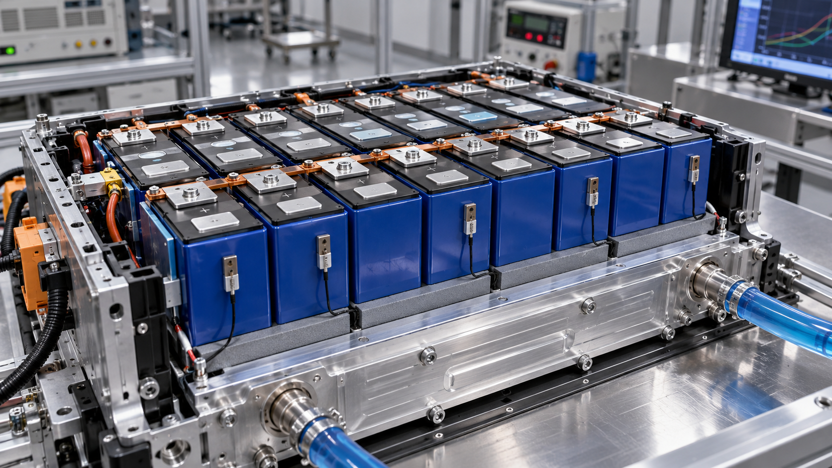
Battery thermal management systems limit fast-charging hot spots by removing heat close to where it forms, distributing cooling across the pack, and reducing charging current before local temperatures exceed validated limits. Their effectiveness depends on the entire path from the cell interior to the vehicle’s heat rejection system. A powerful chiller cannot compensate for poor contact beneath one cell, and a low pack-average temperature cannot establish that every electrical connection is safe.
For technical evaluation, the central question is whether the hottest cell region or connection remains within its permitted operating conditions throughout a realistic charging session. That requires evidence of local temperature control, temperature uniformity, and charging performance together. A pack that stays cool only through substantial current reduction presents a different capability from one that sustains the intended charging profile.
Why fast charging creates local temperature peaks
Battery heat generation changes with current, state of charge, temperature, and cell condition. Resistive losses increase approximately with the square of current when resistance is held constant, making high-current operation particularly sensitive to local resistance. Electrochemical polarization and reversible heat also contribute; cell heat generation cannot be represented accurately by a single fixed resistance across an entire charging session.
These heat sources are distributed unevenly. Current collection geometry can concentrate heating around tabs and terminal regions. Differences in cell impedance or current sharing can produce unequal losses between cells. A busbar joint or weld with elevated contact resistance may create a sharply localized hot spot even when neighboring cell surfaces remain within their expected temperature range.
Cooling introduces another source of variation. Cells near a coolant inlet may experience different boundary conditions from those farther downstream. Parallel cooling branches can receive unequal flow. A gap in a thermal interface, plate deformation, or inconsistent assembly pressure can leave one region with higher thermal resistance than the rest of the module.
Internal cell temperature also differs from measured surface temperature. Heat must travel through the cell structure before reaching a cooling surface or sensor, and that process takes time. During a rapid current ramp, a surface measurement can lag the temperature rise inside the cell. The hottest location can also change as charging progresses.
Technical limits therefore need a clear reference: internal cell temperature, cell surface temperature, terminal temperature, or coolant temperature. These quantities are related, but they are not interchangeable. A temperature spread calculated from a few accessible surface sensors may understate the actual spread within the pack.
Cooling performance depends on the weakest thermal path
Heat removal involves successive steps: conduction through the cell, transfer across the cell-to-cooler interface, conduction through the cooling structure, and convection into the coolant. The coolant must then release that heat through the vehicle thermal system. Each step creates a temperature difference, and an unfavorable section of the path can dominate the local result.
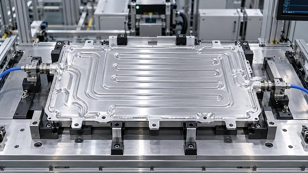
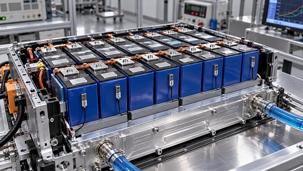
Cooling location should follow the cell’s heat flow characteristics and the pack geometry. Base cooling, side cooling, and cooling between cells create different conduction distances and contact areas. A large cooling surface can still perform poorly if heat must cross a difficult internal path to reach it. Cell format alone does not establish the best arrangement; internal construction, tab location, packaging, and mechanical constraints also matter.
Thermal interface materials bridge tolerances between cells or modules and the cooling structure. Their performance depends on thickness, conductivity, contact area, compression, and durability. Selecting a material by its published conductivity alone misses much of the installed behavior. A thicker layer may accommodate dimensional variation while adding thermal resistance, and uneven compression may create local differences despite an acceptable average bond-line thickness.
These interfaces must also retain their function as cells change dimensions and the pack experiences vibration and thermal cycling. Material displacement, loss of contact, or changes in compression can degrade a design that performed well when newly assembled. Electrical insulation and mechanical protection requirements further constrain the interface; improving heat transfer cannot come at the expense of dielectric integrity.
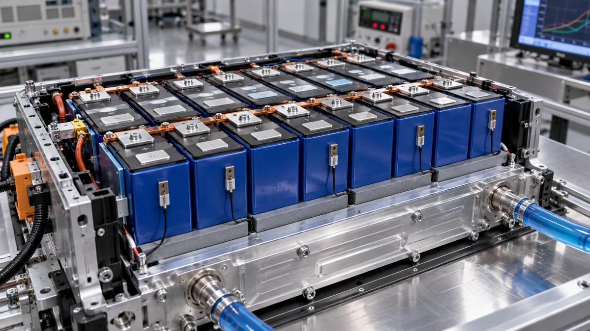
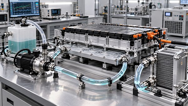
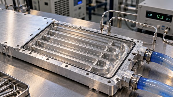
On the coolant side, total flow is only part of the assessment. In a series path, coolant warms as it absorbs heat, potentially reducing the cooling available downstream. Parallel branches can limit this accumulation, but their flow distribution depends on channel resistance, manifold design, tolerances, and air removal. Adequate flow at the pack connection does not prove that every branch receives enough coolant.
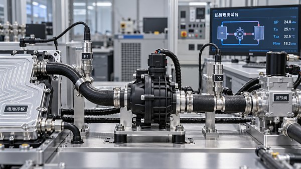
Increasing pump speed may improve convective heat transfer, but the benefit diminishes when cell conduction or interface resistance dominates. Higher flow also carries pressure-drop and auxiliary-power costs. A useful engineering review asks which part of the thermal path causes the temperature peak before prescribing a larger pump or colder coolant.
The vehicle heat rejection system sets a further boundary. When battery cooling uses a refrigerant chiller, available capacity depends on refrigerant operating conditions and other thermal demands, including cabin cooling. A pack tested with an externally controlled coolant supply may perform differently in a vehicle exposed to hot ambient conditions and simultaneous passenger cooling demand.
Sensors and charging controls must cover what cooling cannot
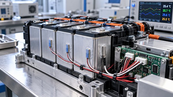
Production sensor coverage is necessarily selective. Sensors should represent predicted hot regions, thermally disadvantaged cells, and locations where a cooling or electrical fault could become consequential. Placing sensors only where installation is convenient can leave gaps around terminals, downstream cooling regions, or poorly cooled module interiors.
Sensor placement should follow thermal mapping and fault analysis. Development packs can carry substantially more instrumentation than production packs, allowing engineers to establish how production measurements relate to harder-to-measure temperatures. Thermal models can then estimate internal conditions, provided their errors and operating boundaries have been assessed.
Measurement uncertainty includes sensor accuracy, mounting quality, sampling interval, filtering, and physical response time. A sensor attached near a terminal may respond differently from one embedded in a module structure. Filtering that stabilizes a displayed temperature can also delay recognition of a rapid rise. Control margins must account for these effects and for the delay between requesting less current and the charger delivering that reduction.
The battery management system coordinates allowable charging current with temperature, state of charge, and other cell limits. The thermal controller adjusts pumps, valves, and refrigeration capacity. Good coordination anticipates the heat load before a local limit is reached. Once a poorly cooled region becomes hot, thermal inertia may keep its temperature elevated even after current falls.
Preconditioning helps establish suitable starting conditions, but its purpose depends on the initial pack state. A cold battery may require heating to support charging without unacceptable lithium-plating risk. A hot battery may need cooling before it can sustain the requested current. Simply lowering coolant temperature as far as possible is not a sound control objective: the appropriate temperature window depends on the cell and charging conditions.
Cooling also cannot correct an electrical defect indefinitely. An abnormal connection resistance requires detection and an appropriate protective response. Strong cooling may suppress the measured surface temperature while leaving the underlying fault unresolved. Thermal protection should therefore work alongside electrical diagnostics and connection-quality controls.
Validation must connect local temperatures to usable charging performance
A credible evaluation begins with a defined operating envelope. The proposed charge profile, initial state of charge, initial battery temperature, ambient conditions, coolant conditions, and vehicle thermal loads should all be recorded. Without those boundaries, a statement that a pack “supports fast charging” offers little basis for comparing designs.
Peak charging power alone is particularly weak evidence. Two systems may reach the same peak briefly while differing substantially in sustained current, local temperature rise, and the point at which thermal limits force tapering. Temperature results should be presented against current, voltage, state of charge, and time so that cooling performance can be distinguished from reduced heat generation caused by derating.
Several measurements deserve to be reviewed together:
- Maximum local temperature: identify the location, measurement method, and relationship to the relevant cell or component limit.
- Temperature spread: define which locations are included and examine how the spread changes throughout the session.
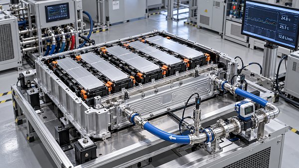
- Coolant conditions: record inlet and outlet temperatures, flow, and pressure drop, with branch measurements where distribution is uncertain.
- Charging behavior: show delivered current and power, thermal derating events, and charging time across the specified state-of-charge interval.
- Control response: establish how quickly the system detects a developing hot region and how effectively cooling or current reduction arrests it.
Pack coolant heat balance can help cross-check total heat removal, but it provides limited information about local peaks. Similarly, infrared imaging can reveal accessible surface patterns during development, yet it cannot directly establish internal cell temperature or inspect regions hidden by the assembled pack. Instrumentation methods should complement one another, with their limitations reflected in the conclusions.
Test coverage should include conditions likely to expose the design’s weaknesses. A hot-soaked pack challenges heat rejection capacity. Charging after demanding driving tests the effect of stored heat. Cold-start charging examines preconditioning and cell constraints. Repeated charging sessions reveal whether the pack and vehicle thermal circuit recover sufficiently between events.
Durability and production variation belong in this assessment. Cell resistance changes with age, while interfaces, joints, and cooling circuits can change through service exposure. Packs representing relevant manufacturing tolerances can reveal contact or flow problems hidden by an ideal development build. Simulation is useful for exploring these variations, but its value depends on correlation with measured local temperatures and realistic boundary conditions.
Fault testing should address credible failures such as restricted coolant flow, trapped air, pump degradation, sensor faults, or valve malfunction. The required outcome depends on the fault: continued operation at reduced current may be acceptable in one case, while another requires charging to stop. The evidence should show that detection and response occur before the affected component exceeds its permitted conditions.
Applicable battery safety and vehicle approval requirements provide a necessary compliance framework. Passing their specified tests, however, does not by itself demonstrate uniform temperatures or sustained fast-charging performance across a vehicle’s intended operating envelope. Evaluators need the test scope, acceptance criteria, and supporting engineering evidence behind each compliance claim.
A useful comparison between thermal designs therefore starts with a shared charging duty and matched boundary conditions. It then follows the hottest locations through the session, including any current reduction needed to control them. If a supplier provides only pack-average temperature and nominal cooling capacity, the unresolved question remains exactly where fast charging places the greatest stress: the cell region, interface, or connection with the least thermal margin.
Core Sector // 01
Recommended News
 Battery Thermal ManagementHow Accurate Do EV Battery Temperature Sensors Need to Be?Battery temperature sensor accuracy goes beyond datasheet tolerance. Discover how placement, response time, and error budgets help you specify the right EV sensors and optimize BMS performance.
 Battery Thermal ManagementHow Do You Test Material Compatibility With EV Coolants?EV coolant material compatibility testing helps prevent leaks, corrosion, and cracking. Learn how to evaluate materials, analyze fluid changes, and validate reliable cooling performance.
 Battery Thermal ManagementHow to choose automotive coolants for an EV battery cooling loopChoose Automotive Coolants for EV battery cooling loops with confidence. Compare heat transfer, conductivity, material compatibility, and OEM requirements to find the right fluid.
 Battery Thermal ManagementHow Do You Calculate EV Battery Cooling Load?EV battery cooling load calculation explained: learn key formulas, follow a worked example, and estimate coolant flow to make informed battery thermal management decisions.
 Battery Thermal ManagementDoes Global Automotive Systems & Components Portal Distinguish Prototype and Production Battery Cooling Plates?Does Global Automotive Systems & Components Portal distinguish battery cooling plate prototypes from series production? Explore GASC’s readiness insights for smarter sourcing decisions.
 Battery Thermal ManagementChoosing a leak test method for battery cooling plate productionBattery Cooling Plates need reliable leak testing. Compare pressure decay, differential pressure, and tracer gas to reduce false rejects and select the right method for your production line.
 Battery Thermal ManagementHow battery thermal management systems limit fast-charging hot spotsBattery Thermal Management Systems limit fast-charging hot spots through targeted cooling and smart controls. Discover how to evaluate thermal safety and sustained charging performance.
 Battery Thermal ManagementHow battery cooling plate channel design affects pressure dropBattery Cooling Plates: Learn how channel depth, bends, and flow paths affect pressure drop. Discover how to balance cooling performance and pump power for smarter plate selection.
 Battery Thermal ManagementSizing automotive electric coolant pumps for system pressure dropSize Automotive Electric Coolant Pumps to match system pressure drop, flow demand, and electrical limits. Discover practical checks to avoid oversizing and ensure reliable vehicle cooling.