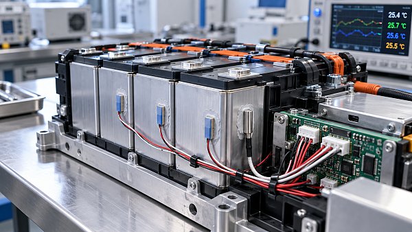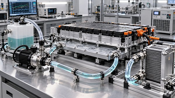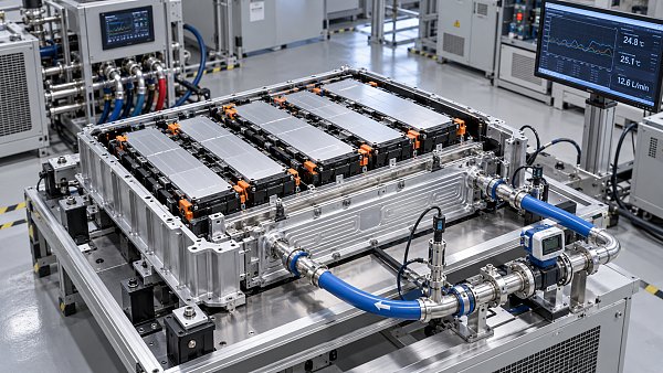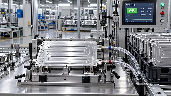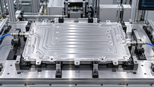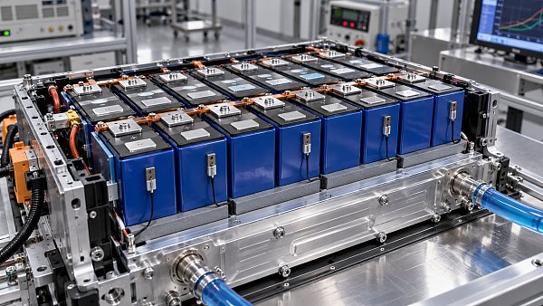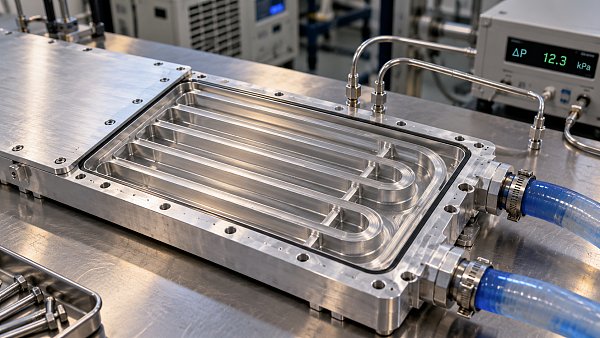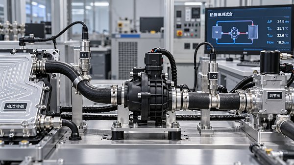
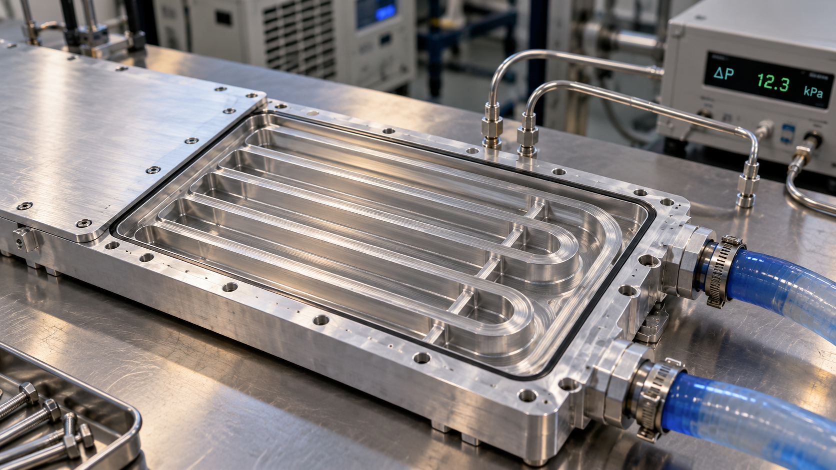
Channel geometry determines how much pumping effort Battery Cooling Plates require, but the lowest pressure drop does not automatically deliver the best battery cooling performance.
For technical evaluators, the useful question is whether a plate meets temperature limits and uniformity targets within the vehicle’s available flow, pressure, and electrical power budgets.
Narrow passages, shallow channels, long routes, and abrupt turns generally increase resistance. Parallel paths can reduce resistance, but their benefit depends on reliable coolant distribution.
Meaningful comparisons therefore require matched coolant properties, operating conditions, and thermal loads. Geometry should be evaluated together with manifolds, manufacturing variation, and the complete cooling circuit.
Which channel dimensions have the greatest effect on pressure drop?
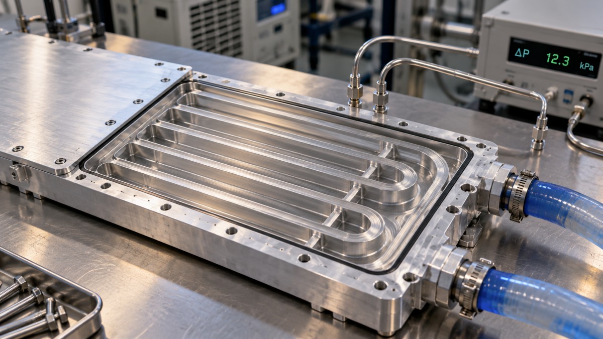
Channel depth often deserves the earliest attention because small reductions can produce large resistance increases. Width matters too, although its influence depends on channel proportions.
For fully developed laminar flow through a shallow rectangular channel, pressure drop approximately scales with viscosity, length, and flow rate, divided by width and depth cubed.
Here, μ is dynamic viscosity, L is channel length, Q is passage flow rate, w is width, and h is depth, with h ≤ w.
This approximation excludes bends, manifolds, entrance effects, and surface features. It is most useful for understanding sensitivity before detailed simulation or physical testing becomes available.
Reducing depth increases velocity and wall friction at a fixed flow rate. In shallow channels, the cubic depth relationship makes packaging compromises especially consequential hydraulically.
Increasing width usually reduces resistance at fixed passage flow, but available plate width is finite. Wider channels may also require structural support against pressure deformation.
Use hydraulic diameter when comparing cross sections, but retain aspect ratio information. Two rectangular passages with equal hydraulic diameter can have different laminar friction characteristics.
For thermal assessment, hydraulic diameter alone is also insufficient: heated perimeter, wall thickness, cell contact area, and thermal boundary conditions influence the resulting heat transfer.
How large can the penalty from a shallower channel become?
Consider an illustrative straight passage measuring 10 millimeters wide, 2 millimeters deep, and 1 meter long, carrying 1 liter per minute through that individual passage.
Assume coolant dynamic viscosity of 3 millipascal seconds and density of 1,050 kilograms per cubic meter. These are calculation inputs, not universal coolant specifications.
The mean velocity is approximately 0.83 meters per second, and hydraulic diameter is 3.33 millimeters. The resulting Reynolds number is approximately 970, consistent with laminar flow.
Using the rectangular channel approximation gives about 8.6 kilopascals of straight passage pressure drop. Actual plate losses would additionally include ports, turns, entrances, and manifolds.
Reducing depth to 1 millimeter while maintaining passage flow raises the estimated straight passage loss to approximately 64 kilopascals, roughly 7.5 times the original value.
The shallower passage also changes velocity and heat transfer behavior. That hydraulic penalty only makes sense if its thermal or packaging benefit justifies the demand.
These numbers should not become a purchasing specification. Their purpose is to show why apparently modest depth changes require hydraulic reassessment before tooling decisions become fixed.
When do channel length and bends dominate the result?
For a constant cross section and flow regime, straight channel friction increases approximately with length. A longer serpentine route therefore carries a predictable hydraulic penalty.
Serpentine routing forces coolant through a defined path, limiting opportunities for branch maldistribution. However, coolant warms along that path, potentially increasing downstream cell temperatures.
Turns introduce additional losses through separation, secondary flow, and redevelopment. Tight bends and abrupt direction changes generally demand more pressure than gradual transitions at comparable conditions.
A useful engineering decomposition separates distributed friction from local losses, while recognizing that bend coefficients can depend strongly on Reynolds number and detailed geometry.
The equation uses the Darcy friction factor. Mixing Darcy and Fanning friction factors introduces a factor of four error, so calculation conventions must remain explicit.
Each local loss coefficient must reference the appropriate local velocity. Using channel velocity for a restrictive inlet fitting can substantially underestimate the complete plate pressure drop.
Ribs, dimples, and other mixing features can improve convection while increasing resistance. Their value should be demonstrated through thermal performance at an acceptable pumping requirement.
Do parallel channels always reduce pressure drop?
Parallel channels divide total plate flow among multiple paths. With identical branches and balanced distribution, each branch carries less flow and typically develops lower friction losses.
For laminar branches of unchanged geometry, dividing a fixed total flow equally among more passages reduces individual branch pressure drop approximately in proportion to branch flow.
However, adding branches within the same footprint often requires narrower passages or altered manifolds. Those changes can offset part of the theoretical benefit of parallelization.
The pressure drops across parallel branches are not added together. Instead, each branch connects between local manifold pressures, while inlet and outlet routing add system losses.
Distribution becomes critical when manifold pressure variation is significant relative to branch resistance. Some passages may receive excessive flow while others develop thermally important starvation.
Extremely low branch resistance can therefore make balancing harder. Deliberate restrictions may improve distribution, although they consume pressure budget and must remain robust against contamination.
Request branch flow predictions and temperature maps alongside the total pressure curve. A favorable average outlet temperature can conceal inadequate cooling beneath individual cell groups.
For plates connected in parallel across a pack, repeat this assessment at the pack manifold level. Plate uniformity does not guarantee equal flow between plates.
Why must coolant temperature and pump behavior be included?
Coolant viscosity changes with temperature and mixture concentration. A plate that satisfies pressure targets with warm coolant may impose substantially greater resistance during cold operation.
Use the specified coolant formulation and its temperature dependent properties. Water based laboratory results need correction or confirmation before representing the intended water glycol mixture.
Reynolds number helps identify the flow regime, but transitions depend on geometry and disturbances. Avoid assuming that every battery cooling passage remains laminar throughout operation.
In fully developed laminar flow with fixed properties, pressure drop generally varies linearly with flow. In turbulent or locally dominated conditions, the relationship becomes steeper.
A vehicle pump does not necessarily maintain the same flow after a plate redesign. Its operating point follows the interaction between pump and circuit characteristics.
Higher plate resistance can therefore reduce delivered coolant flow, unless pump speed increases. That response affects thermal margin, electrical consumption, and potentially noise and durability.
Hydraulic power equals pressure drop multiplied by volumetric flow. Electrical input additionally depends on pump and drive efficiency at the actual operating point being evaluated.
Set the plate pressure allowance after accounting for hoses, valves, heat exchangers, filters, connectors, and elevation effects where relevant. Confirm adequate pump inlet conditions separately.
How should hydraulic performance be weighed against battery temperature?
Compare designs at the same heat input, coolant inlet temperature, and defined flow condition first. Then examine their behavior under the vehicle’s actual pump control strategy.
The coolant energy balance provides an essential check: bulk temperature rise depends on heat transferred, mass flow rate, and specific heat capacity under steady conditions.
This balance does not predict maximum cell temperature by itself. Interface resistance, plate conduction, local convection, and uneven cell heat generation determine temperatures within the pack.
Evaluate maximum temperature and temperature spread together with pressure drop. Lower resistance is valuable when it preserves thermal performance or enables worthwhile reductions in pumping demand.
Higher velocity does not guarantee a proportional improvement in heat transfer. For some fully developed laminar conditions, the Nusselt number depends primarily on geometry and boundary conditions.
Compare candidate plates at matched pumping power as an additional assessment. This can reveal whether a thermally stronger design still offers an advantage after hydraulic costs.
Include representative fast charging, sustained driving, and transient loads where applicable. A geometry optimized for one steady operating point may provide insufficient margin elsewhere in service.
Which manufacturing details can invalidate the predicted pressure drop?
Nominal CAD geometry is only a starting point. Forming variation, joining distortion, internal braze accumulation, and channel collapse can alter the effective flow area materially.
Depth tolerances deserve particular scrutiny in shallow passages. A small absolute deviation can represent a large percentage change and materially increase resistance or disturb branch balance.
For example, a ten percent depth reduction produces roughly a thirty seven percent resistance increase under the shallow channel cubic approximation, before aspect ratio corrections.
Surface roughness also matters, but its influence depends on flow regime and relative roughness. Do not apply turbulent roughness penalties indiscriminately to smooth laminar passages.
Pressure loading can deform thin walls and change passage dimensions. Evaluate geometry under relevant operating pressure when compliance could meaningfully affect hydraulic and mechanical behavior.
Ask suppliers how production controls verify internal geometry and cleanliness. Nominal dimensions alone cannot establish resistance to debris accumulation, blocked passages, or manufacturing related flow restriction.
Use samples spanning credible dimensional variation for validation. A single prototype with favorable geometry provides limited evidence that production plates will meet the same hydraulic target.
What evidence should technical evaluators request before selecting a plate?
Request pressure drop curves over the intended flow range, with coolant identity, concentration, and temperature recorded. Define whether measurements include ports, connectors, and external fixtures.
Require a clear pressure tap arrangement and test uncertainty. Fixture losses, trapped air, inconsistent stabilization, or temperature drift can obscure meaningful differences between competing plates.
Pair hydraulic curves with thermal results under documented heat loads and contact conditions. Request maximum surface temperature, temperature distribution, coolant temperature rise, and branch balance evidence.
Simulation should use appropriate coolant properties, boundary conditions, and flow models. Correlation against physical measurements is particularly important for manifolds, turns, and complex internal enhancements.
Select Battery Cooling Plates that meet thermal requirements across operating conditions and production variation within the available pump budget. Treat pressure drop as a coupled design constraint.
The strongest candidate delivers acceptable temperatures, predictable coolant distribution, and repeatable manufacturing quality. Its hydraulic performance remains credible when evaluated within the complete vehicle cooling circuit.