Battery Thermal Management
Navigation
Send Us A Message
Sizing automotive electric coolant pumps for system pressure drop
Author
Date Published
Reading Time
Sizing automotive electric coolant pumps for system pressure drop
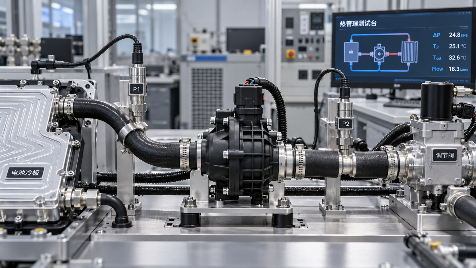
Selecting Automotive Electric Coolant Pumps starts with the cooling circuit—not the pump’s maximum flow rating. Battery packs, power electronics, heat exchangers, valves, and hoses create pressure losses that change with flow rate, coolant temperature, and operating mode. The task is to match the pump curve to the system resistance curve while checking electrical power demand, control capability, and cavitation margin. A defensible selection therefore needs realistic duty points, credible pressure-drop data, and supplier performance maps that reflect the intended installation.
A pump can look comfortably sized on a datasheet and still miss the vehicle’s thermal target. Free-flow capacity says little about performance against a restrictive battery cold plate. Conversely, selecting for the highest conceivable resistance can produce unnecessary current draw and poor low-load control. The useful question is not “How much can this pump move?” but “What will it deliver through this circuit under the conditions that matter?”
Define the thermal duty before calculating hydraulic resistance
Begin with the heat that each circuit must transport and the allowable coolant temperature rise. For a steady-state energy balance, heat transfer rate equals mass flow multiplied by specific heat capacity and coolant temperature rise. Converting mass flow to volumetric flow also requires coolant density. Both properties must correspond to the specified coolant mixture and temperature.
This calculation establishes a starting flow requirement, not a complete cooling specification. Battery temperature uniformity, cold-plate distribution, local heat-transfer coefficients, and semiconductor temperature limits may demand more flow than the bulk energy balance suggests. Component suppliers should provide minimum-flow requirements and explain the thermal boundary conditions behind them.
Build separate duty points for operating modes that change the hydraulic path or thermal demand. Fast charging, sustained traction load, battery conditioning, and low-load operation may involve different valve positions and active heat exchangers. Do not combine the maximum heat load from one mode with the maximum resistance from another unless those conditions can actually occur together.
Each duty point should identify required branch flow, coolant temperature and concentration, valve configuration, available supply voltage, and permitted operating duration. Transient demands also need an allowable response time. These details turn a vague requirement for “adequate cooling” into something a supplier can demonstrate.
Build a system curve, not a single pressure-drop estimate
For a series circuit, total pressure loss is the sum of the losses through each component at the same flow. Include cold plates, radiators or chillers, valves, connectors, hoses, bends, and other restrictions. A collection of nominal component values is useful only when the underlying flow, fluid, and temperature conditions are compatible.
In predominantly turbulent flow, pressure drop is often approximated as proportional to flow squared. That makes a resistance curve straightforward to estimate, but the approximation has limits. Narrow passages, viscous coolant, and changing flow regimes can alter the relationship. Use measured component curves where available, especially for cold plates and control valves that dominate circuit resistance.
Parallel branches require a network calculation. Branches between common junctions experience the same junction-to-junction pressure difference, but they do not necessarily receive equal flow. A low-resistance bypass can carry substantial flow while a restrictive battery branch remains below its requirement. Total pump flow alone will not reveal that problem.
Elevation also needs careful treatment. In a fully filled, closed recirculating loop, elevation gains and losses balance around the circuit; the pump does not continuously overcome the vehicle’s full vertical height as static lift. Local elevation still affects absolute pressure, filling, air removal, and suction conditions. Open or partially filled operating conditions require separate analysis.
Find the intersection—and check what moves it
A centrifugal coolant pump operates where its pressure-flow curve intersects the system resistance curve. Maximum flow is generally quoted near very low differential pressure, while shutoff pressure occurs at zero flow. Neither endpoint describes the required operating point.
Overlay the system curves for relevant valve configurations on supplier pump curves at the available speeds. If the supplier reports head rather than pressure, convert using pressure difference = density × gravitational acceleration × head. Keep units and coolant density consistent; otherwise, two apparently comparable curves may represent different hydraulic conditions.
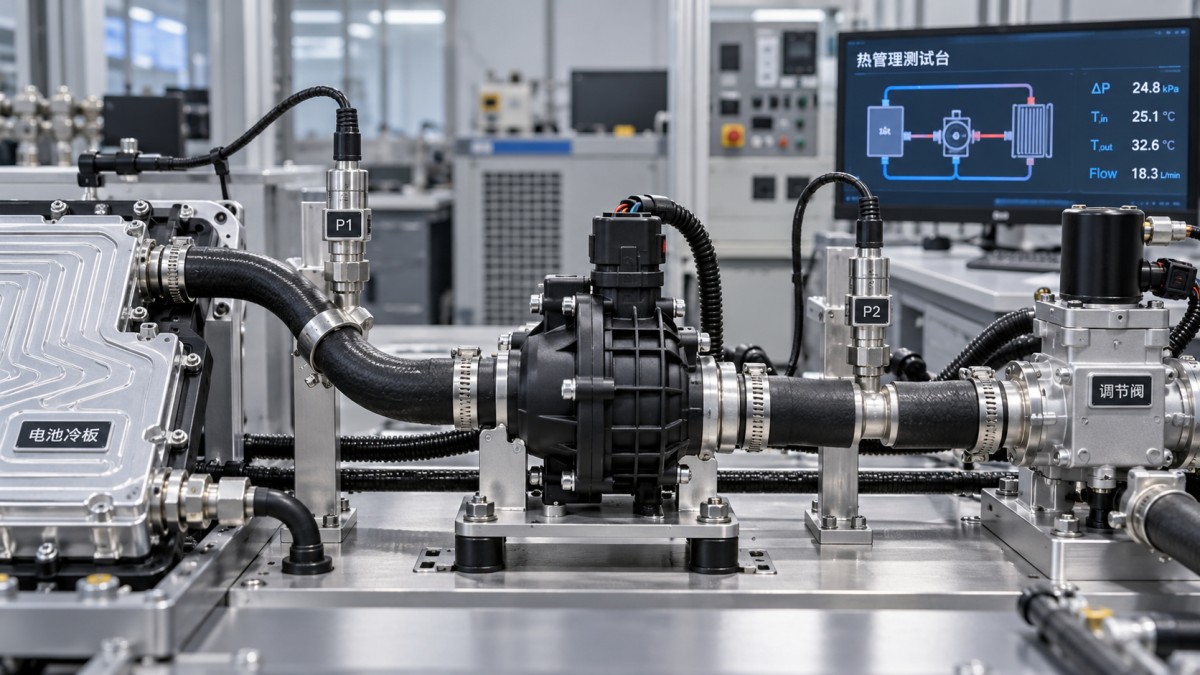
The useful selection envelope includes both demanding and routine operation. Check whether the pump can reach the critical high-resistance duty point, but also whether it can regulate the lowest required flow without unstable cycling, unacceptable noise, or excessive bypass flow. A larger pump is not automatically more adaptable.
Speed-scaling relationships can support early screening: for a geometrically unchanged pump under similar conditions, flow scales approximately with speed, head with speed squared, and shaft power with speed cubed. These relationships are not substitutes for measured maps. Electronic current limits, motor heating, viscosity, and controller behavior can constrain the installed pump before ideal scaling predicts a limit.
Separate cold-flow resistance from hot-fluid suction risk
Cold coolant can increase circuit resistance substantially because viscosity rises. The resulting operating point depends on both the changed system curve and the pump’s performance with that fluid. A room-temperature water test should not be accepted as proof of cold-start capability for a glycol-based production mixture.
Hot operation presents a different concern. As coolant vapor pressure rises, the margin against cavitation can shrink. Assess net positive suction head available against the supplier’s required value, with an appropriate project-defined margin. Use absolute inlet pressure and account for coolant vapor pressure, suction-line losses, reservoir conditions, installation height, and applicable altitude conditions.
If the supplier does not publish NPSH data, request the minimum inlet-pressure envelope and its test basis. A cavitation criterion based on measurable performance loss does not necessarily guarantee freedom from noise, erosion, or durability concerns. The acceptance criterion must match the vehicle requirement.
Entrained air deserves separate attention. Vapor cavitation and air ingestion are not the same mechanism, and improving inlet pressure will not correct every air-handling problem. Review reservoir connections, high points, deaeration paths, and fill procedures. A pump that passes a fully flooded bench test may behave differently during vehicle filling or after service.
Check electrical demand at the actual hydraulic duty
Hydraulic power equals volumetric flow multiplied by pressure rise. Electrical input is higher because pump, motor, and controller efficiencies are below unity and vary across the operating map. Compare candidates using measured electrical input at the required duty points, rather than rated wattage or a single peak-efficiency figure.
The vehicle’s electrical architecture can change the result. Confirm performance at minimum available terminal voltage, including harness voltage drop, and at relevant coolant and electronics temperatures. Establish whether thermal protection or current limiting reduces speed during a sustained duty. A pump that reaches the target briefly may not sustain it through a charging event or prolonged high-load operation.
Control interfaces also need practical scrutiny. A speed command does not guarantee coolant flow when resistance changes. Determine what feedback is available—actual speed, current, temperature, fault status, or a validated flow estimate—and how the thermal controller detects degraded circulation. Define behavior after communication loss, blocked-rotor detection, undervoltage, and recovery from protective shutdown.
Where the pump operates frequently at partial load, assess energy use across representative operating modes. Peak capability remains a pass/fail constraint, but it should not be the only basis for comparing technically compliant candidates.
Ask suppliers for evidence that survives installation
A useful supplier package makes its assumptions visible. Before shortlisting Automotive Electric Coolant Pumps, request evidence covering the following points:
- Pressure-flow and electrical-input maps with coolant composition, temperature, voltage, speed, and measurement locations stated.
- Performance tolerances and whether curves represent typical output or guaranteed minimum capability.
- Continuous operating limits, derating behavior, inlet-pressure requirements, and air-handling restrictions.
- Materials compatibility and durability evidence relevant to the specified coolant, temperature cycles, vibration, and installation environment.
- Production change controls for hydraulic geometry, motor, electronics, and software that could affect approved performance.
Then validate the assembled circuit. Measure pressure across major restrictions and verify branch flow where distribution matters. Compare the measured operating point with the model before adjusting pump size. A partially opened valve, kinked hose, trapped air pocket, or unrepresentative prototype connector can otherwise lead to the wrong corrective action.
Apply margin to identified uncertainties rather than adding overlapping allowances everywhere. Component pressure-drop tolerance, manufacturing variation, and anticipated service-related changes should each have a stated basis. Keep expected, tolerance-limit, and fault conditions distinguishable so that the resulting specification remains testable.
Make the selection traceable to vehicle requirements
The final decision should link each critical vehicle mode to a required branch flow, predicted pressure drop, demonstrated pump capability, electrical demand, and validation result. Where evidence is missing, record the gap rather than hiding it inside a larger pump specification.
This component-to-platform view fits GASC’s planned role as an independent automotive systems and components portal: evaluating selection against thermal loads, electrical architecture, validation, manufacturing quality, and sourcing risk rather than isolated catalogue ratings. An alternate supplier’s pump is not equivalent merely because its maximum flow matches; its operating map, control behavior, and qualified configuration must also align.
Before releasing the specification, resolve three questions: does every required branch receive sufficient flow, can the pump sustain that duty within electrical and suction limits, and can production hardware reproduce the validated result? Those answers provide a stronger selection basis than the largest flow number on the datasheet.
- Last One:How battery cooling plate channel design affects pressure dropOct 28, 2026
- Next Article:No more articles
Core Sector // 01
Recommended News
 Battery Thermal ManagementHow Accurate Do EV Battery Temperature Sensors Need to Be?Battery temperature sensor accuracy goes beyond datasheet tolerance. Discover how placement, response time, and error budgets help you specify the right EV sensors and optimize BMS performance.
 Battery Thermal ManagementHow Do You Test Material Compatibility With EV Coolants?EV coolant material compatibility testing helps prevent leaks, corrosion, and cracking. Learn how to evaluate materials, analyze fluid changes, and validate reliable cooling performance.
 Battery Thermal ManagementHow to choose automotive coolants for an EV battery cooling loopChoose Automotive Coolants for EV battery cooling loops with confidence. Compare heat transfer, conductivity, material compatibility, and OEM requirements to find the right fluid.
 Battery Thermal ManagementHow Do You Calculate EV Battery Cooling Load?EV battery cooling load calculation explained: learn key formulas, follow a worked example, and estimate coolant flow to make informed battery thermal management decisions.
 Battery Thermal ManagementDoes Global Automotive Systems & Components Portal Distinguish Prototype and Production Battery Cooling Plates?Does Global Automotive Systems & Components Portal distinguish battery cooling plate prototypes from series production? Explore GASC’s readiness insights for smarter sourcing decisions.
 Battery Thermal ManagementChoosing a leak test method for battery cooling plate productionBattery Cooling Plates need reliable leak testing. Compare pressure decay, differential pressure, and tracer gas to reduce false rejects and select the right method for your production line.
 Battery Thermal ManagementHow battery thermal management systems limit fast-charging hot spotsBattery Thermal Management Systems limit fast-charging hot spots through targeted cooling and smart controls. Discover how to evaluate thermal safety and sustained charging performance.
 Battery Thermal ManagementHow battery cooling plate channel design affects pressure dropBattery Cooling Plates: Learn how channel depth, bends, and flow paths affect pressure drop. Discover how to balance cooling performance and pump power for smarter plate selection.
 Battery Thermal ManagementSizing automotive electric coolant pumps for system pressure dropSize Automotive Electric Coolant Pumps to match system pressure drop, flow demand, and electrical limits. Discover practical checks to avoid oversizing and ensure reliable vehicle cooling.