Battery Thermal Management
Navigation
Send Us A Message
How Do You Calculate EV Battery Cooling Load?
Author
Date Published
Reading Time
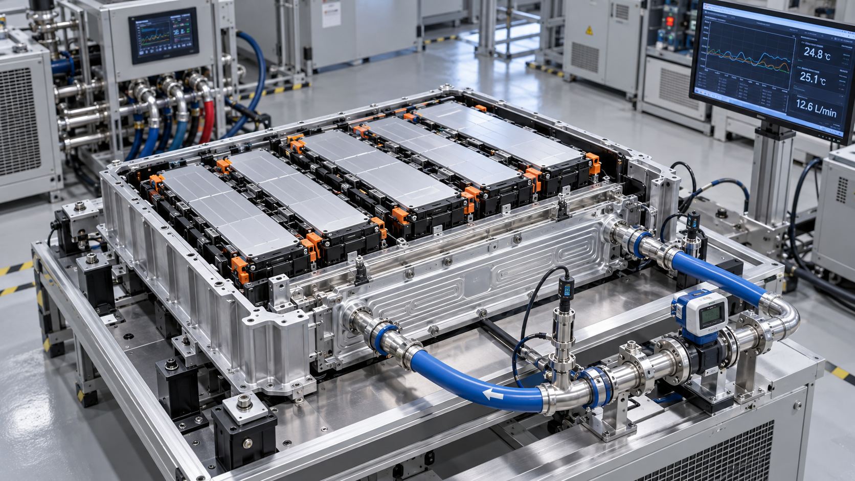
Calculate EV battery cooling load by adding the heat generated inside the pack and the heat entering from its surroundings, then accounting for any required reduction in stored thermal energy. For a simplified pack model, the required heat removal rate is:
Q̇cool = Q̇gen + Q̇env − Cth(dT/dt)
Here, Q̇ denotes heat flow in watts, Cth is effective pack thermal capacitance in joules per kelvin, and T is representative pack temperature. Environmental heat flow is positive when heat enters the pack. During cooldown, dT/dt is negative, so the cooling requirement increases. Battery capacity alone cannot establish this load: current, resistance, temperature, state of charge, and the operating timeline determine the result.
Which operating conditions define the cooling requirement?
Start with a time-based operating case. A sustained highway climb, repeated acceleration, and fast charging produce different current profiles and different opportunities to reject heat. Record pack current, state of charge, initial temperature, ambient conditions, coolant inlet temperature, and the allowable cell temperature throughout each case.
The temperature requirement needs two limits: the maximum permitted cell temperature and the permitted temperature difference across the pack. An acceptable average temperature can conceal a hot cell near a poorly supplied coolant branch. A cooling load calculation establishes the quantity of heat to remove; a thermal distribution model establishes whether that removal reaches the cells that need it.
Evaluate conditions that can occur together. A hot pack arriving at a fast charger has both ongoing heat generation and a cooldown requirement. Conversely, combining the highest driving current with the highest charging current creates an operating condition that cannot occur. Build capacity requirements around credible combinations and their duration.
How is battery heat generation calculated?
A useful first estimate for irreversible electrical heating is:
Q̇irr = Ipack2Rpack
Use current in amperes and resistance in ohms to obtain watts. Resistance must correspond to the relevant temperature, state of charge, state of health, and measurement timescale. A short-pulse resistance value does not automatically represent losses during a sustained charging event, because polarization develops over time.
For identical cells arranged in Ns series positions and Np parallel paths, an idealized equivalent resistance is:
Rcells = NsRcell/Np
Add busbar, weld, connector, contactor, and other relevant conductor losses if they fall inside the thermal boundary. Their location matters: heat generated in a junction enclosure might enter a different cooling path from heat generated inside cell modules. Unequal current sharing also makes the ideal parallel-cell calculation less representative of local heating.
For greater accuracy, include reversible, or entropic, heat. With discharge current defined as positive, a common cell-level expression is:
Q̇cell = I(UOCV − V) − IT(∂UOCV/∂T)
UOCV is equilibrium open-circuit voltage, V is terminal voltage, and T is absolute temperature in kelvin. The first term represents irreversible losses; the second represents reversible heat. The entropy coefficient varies with chemistry and state of charge, so this term can either increase or reduce net heat generation.
Keep the current sign convention consistent during charging. Also avoid adding I2R to the entire voltage-loss term: these are alternative representations of overlapping irreversible losses. Where a dynamic electrical model already predicts polarization losses, use its energy accounting consistently.
Can average current represent a changing drive cycle?
For approximately constant resistance, average resistive heating follows mean-square current:
Q̇irr,avg = R × mean(I2) = RIRMS2
Squaring average current underestimates heating when current fluctuates. Acceleration and regenerative braking can produce substantial heat even when their signed currents partly cancel. If resistance changes significantly during the cycle, calculate I(t)2R(t) at each timestep and integrate. Brief peaks can be buffered by pack thermal mass, provided local cell temperatures remain within limits.
What environmental and cooldown loads belong in the balance?
For a preliminary estimate, environmental heat transfer through the pack enclosure can be represented as:
Q̇env = UA(Tsurroundings − Tpack)
Here, UA is overall thermal conductance in watts per kelvin. This approximation combines conduction and external heat transfer into one parameter. Underbody airflow, shielding, enclosure construction, and nearby hot components affect its value. Radiation requires separate treatment when a single effective surroundings temperature cannot represent the exposure.
Environmental heat flow can be negative. When the surroundings are cooler than the pack, passive heat rejection reduces active cooling demand. However, using road-speed airflow to size a stationary charging condition would overstate that benefit. Solar exposure and hot pavement should be represented through relevant surface temperatures and heat-transfer paths, rather than added as arbitrary loads.
To estimate the extra capacity required for cooldown over a specified period:
Q̇pull-down,avg = Cth(Tinitial − Ttarget)/tcooldown
Estimate effective thermal capacitance from the masses and specific heat capacities of participating cells, structures, coolant, and other components. A heavy enclosure that exchanges heat slowly with the cells might contribute little during a short event. Treating every pack component as instantly uniform can therefore underpredict cell temperature rise.
This expression gives an average sensible cooling requirement. Actual cooldown slows as the temperature difference between cells and coolant decreases. A transient model is needed to establish whether the target temperature can be reached within the specified time.
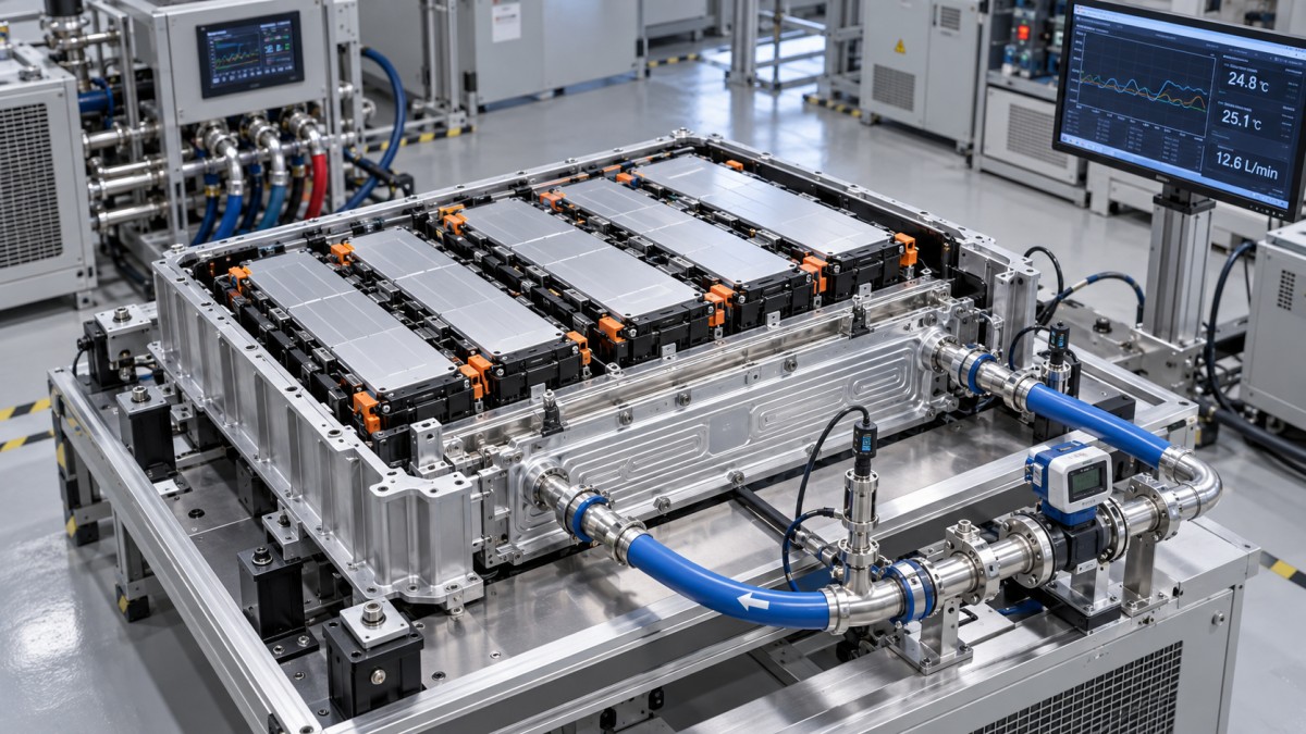
What does a worked cooling-load calculation look like?
Consider a hypothetical operating point with the following assumed inputs. These values illustrate the method; they are not specifications for a particular battery.
Assuming reversible heat is negligible for this illustration, electrical heating is 3002 × 0.040 = 3.60 kW. The average cooldown term is 400 × 5 / 1,200 = 1.67 kW. Adding environmental heat gain gives:
Q̇cool,avg = 3.60 + 0.40 + 1.67 = 5.67 kW
If pack temperature only needs to remain constant, the cooldown term disappears and the same operating point requires 4.00 kW. This difference shows why a temperature target must include a timeline.
The 5.67 kW result assumes constant heat generation and environmental gain throughout the interval. Charging taper, changing resistance, and changing temperature differences require timestep calculations. It also represents heat extracted from the pack; downstream pipe heat gains and pump heat entering the coolant require separate accounting when sizing the chiller.
How does cooling load translate into coolant flow?
For single-phase liquid cooling, the coolant-side energy balance is:
Q̇ = ṁcp(Tout − Tin)
Using the illustrative 5.67 kW load, an assumed coolant specific heat of 3.6 kJ/(kg·K), and an allowable coolant rise of 5 K gives:
ṁ = 5.67 / (3.6 × 5) = 0.315 kg/s
Convert mass flow to volumetric flow using coolant density at the relevant temperature. Both density and specific heat depend on coolant composition and temperature; pure-water properties should not be substituted for a glycol mixture without justification.
This equation determines the flow needed to carry heat away at the chosen temperature rise. It does not prove that the cold plate can transfer that heat from the cells. Cell-to-coolant thermal resistance creates an additional temperature difference, which can be approximated locally as Q̇localRθ. Interface thickness, contact pressure, channel geometry, and flow distribution affect that resistance.
Increasing flow generally raises pressure loss and pump power, while improvements in cell temperature eventually diminish as other thermal resistances dominate. Evaluate the pump operating point against the complete circuit pressure drop, including manifolds, hoses, valves, and the chiller. Parallel branches require flow-distribution analysis because adequate total flow can coexist with an undercooled module.
Is the battery cooling load the required chiller capacity?
The chiller must absorb the battery-loop load plus any additional heat entering that loop. Its available capacity must be evaluated at the specified coolant and refrigerant operating conditions. A nominal capacity measured with warmer coolant or more favorable heat rejection conditions does not establish performance during hot-weather fast charging.
A radiator can reject heat when coolant is sufficiently warmer than ambient air. If the required coolant supply temperature is below ambient, that passive path cannot achieve the target by itself. Refrigerant-assisted cooling is then required for that operating condition.
In a shared refrigerant system, simultaneous cabin demand affects compressor operation and available battery cooling. Assess the actual refrigerant architecture and control priorities. Battery heat load alone does not establish compressor electrical power, which depends on system efficiency and operating temperatures.
Thermal storage can reduce the capacity needed for a brief peak. Quantify this by integrating the difference between generated heat and extracted heat, then calculating the resulting temperature rise. The hottest cell and subsequent recovery period govern whether that temporary imbalance is acceptable.
How should the calculation be validated?
Compare predicted heat rejection with measured coolant mass flow and inlet-to-outlet temperature rise under controlled conditions. During transients, coolant heat removal will differ from instantaneous battery heat generation because energy is being stored in, or released from, the pack. Temperature measurements across modules are needed to distinguish acceptable bulk behavior from local overheating.
Measurement uncertainty becomes significant when coolant temperature rise is small. Matched temperature sensors, representative sensor placement, and a characterized flow meter improve the usefulness of the energy balance. Include pump heat and external pipe heat transfer when the measurement boundary contains them.
Repeat the assessment using resistance and thermal-interface conditions representative of the intended service life. Resolve uncertainty through measured parameter ranges and sensitivity analysis before adding capacity margin. A larger chiller cannot correct poor cell contact or coolant maldistribution; validation must establish both sufficient heat-removal capacity and an acceptable maximum cell temperature.
Core Sector // 01
Recommended News
 Battery Thermal ManagementHow Accurate Do EV Battery Temperature Sensors Need to Be?Battery temperature sensor accuracy goes beyond datasheet tolerance. Discover how placement, response time, and error budgets help you specify the right EV sensors and optimize BMS performance.
 Battery Thermal ManagementHow Do You Test Material Compatibility With EV Coolants?EV coolant material compatibility testing helps prevent leaks, corrosion, and cracking. Learn how to evaluate materials, analyze fluid changes, and validate reliable cooling performance.
 Battery Thermal ManagementHow to choose automotive coolants for an EV battery cooling loopChoose Automotive Coolants for EV battery cooling loops with confidence. Compare heat transfer, conductivity, material compatibility, and OEM requirements to find the right fluid.
 Battery Thermal ManagementHow Do You Calculate EV Battery Cooling Load?EV battery cooling load calculation explained: learn key formulas, follow a worked example, and estimate coolant flow to make informed battery thermal management decisions.
 Battery Thermal ManagementDoes Global Automotive Systems & Components Portal Distinguish Prototype and Production Battery Cooling Plates?Does Global Automotive Systems & Components Portal distinguish battery cooling plate prototypes from series production? Explore GASC’s readiness insights for smarter sourcing decisions.
 Battery Thermal ManagementChoosing a leak test method for battery cooling plate productionBattery Cooling Plates need reliable leak testing. Compare pressure decay, differential pressure, and tracer gas to reduce false rejects and select the right method for your production line.
 Battery Thermal ManagementHow battery thermal management systems limit fast-charging hot spotsBattery Thermal Management Systems limit fast-charging hot spots through targeted cooling and smart controls. Discover how to evaluate thermal safety and sustained charging performance.
 Battery Thermal ManagementHow battery cooling plate channel design affects pressure dropBattery Cooling Plates: Learn how channel depth, bends, and flow paths affect pressure drop. Discover how to balance cooling performance and pump power for smarter plate selection.
 Battery Thermal ManagementSizing automotive electric coolant pumps for system pressure dropSize Automotive Electric Coolant Pumps to match system pressure drop, flow demand, and electrical limits. Discover practical checks to avoid oversizing and ensure reliable vehicle cooling.