EV battery temperature sensors need accuracy matched to the battery’s control margins. A tighter sensor tolerance helps only when installation and electronics preserve that advantage.
As an initial engineering target, teams may evaluate ±1°C installed measurement accuracy around critical control thresholds. This is an illustrative target, not a universal requirement.
Some applications need tighter uncertainty; others can tolerate more. The answer depends on chemistry, charging strategy, thermal gradients, response time, and the consequences of measurement error.
For engineers and sourcing teams, battery temperature sensor accuracy therefore means more than datasheet tolerance. The useful specification describes what the BMS can reliably know.
What Accuracy Should You Specify First?
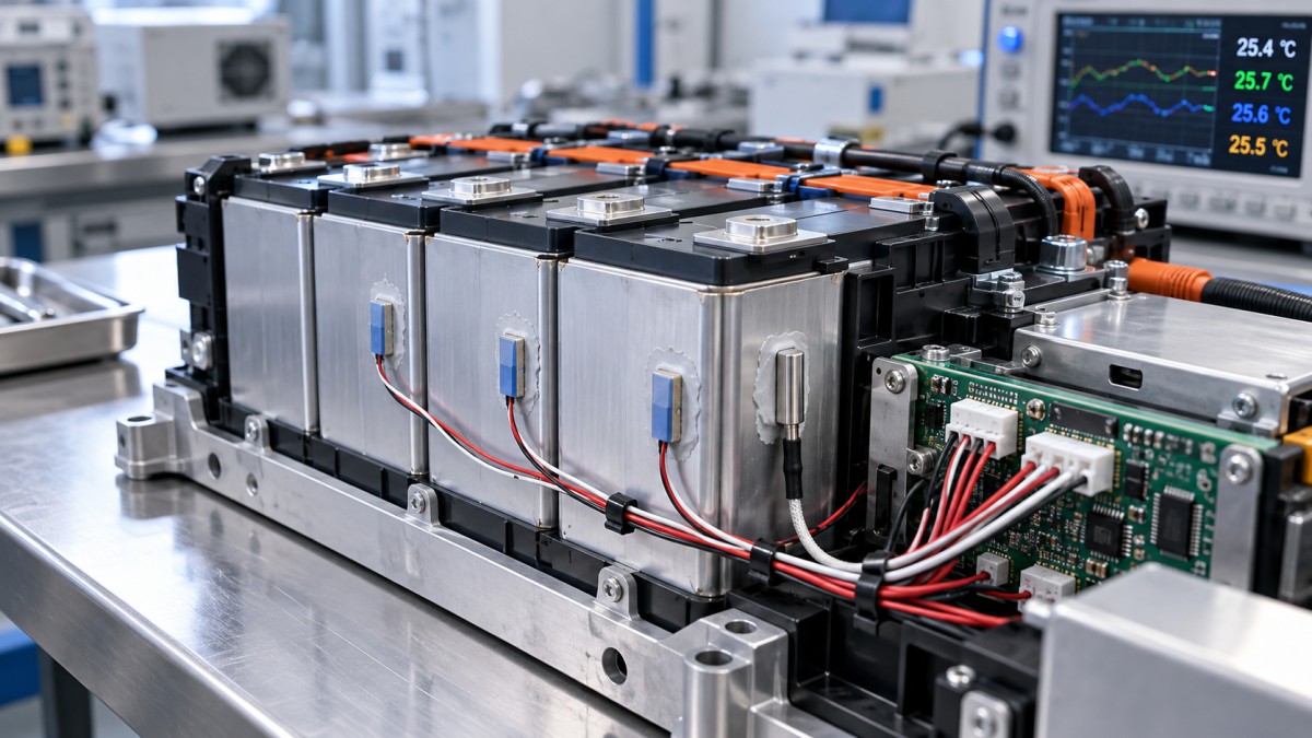
Start with the temperature information required for a control decision: the measured surface temperature, an estimated internal cell temperature, or a representative module temperature.
These quantities are related but interchangeable only under validated conditions. A precise surface reading can still underestimate internal cell temperature during demanding operation or fast charging.
Define the allowable uncertainty for each decision separately. Cooling activation, charging derating, cold-charge permission, and protective shutdown may require different margins and different response times.
The following framework helps translate operating conditions into requirements. It identifies specification priorities without presenting any single accuracy figure as an industry-wide acceptance limit.
A useful requirement might specify ±1°C at defined mounting locations across a limited control band, with separate limits elsewhere. Its validity must come from system analysis.
Avoid requesting “±1°C accuracy” without defining temperature range, measurement location, electrical conditions, aging allowance, and verification method. Suppliers could otherwise interpret the same requirement differently.
Why Datasheet Accuracy Does Not Equal Battery Temperature Accuracy
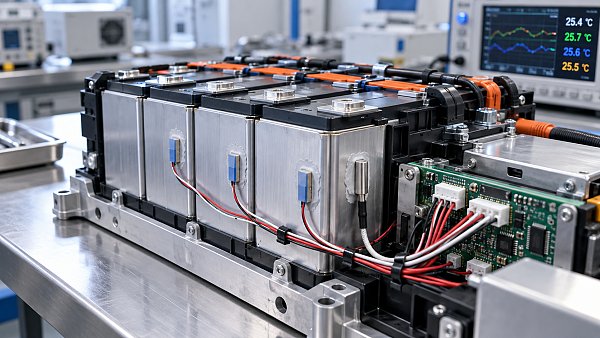
A temperature measurement chain includes the sensing element, wiring, connectors, excitation circuit, conversion electronics, software, and thermal interface. Each can affect the reported temperature value.
For an NTC thermistor, resistance tolerance at a reference temperature does not establish accuracy across the operating range. Resistance-temperature curve variation also affects conversion accuracy.
The divider resistor, ADC behavior, leakage currents, and conversion algorithm introduce additional errors. A ratiometric circuit can reduce reference-related sensitivity, depending on its implementation.
Sensor self-heating creates another offset. Its magnitude depends on measurement power, duty cycle, and heat dissipation through the installed sensor assembly and surrounding materials.
Repeatability also differs from absolute accuracy. A channel may produce stable readings while maintaining a systematic offset that shifts every charging or cooling decision.
Calibration can correct selected electrical offsets, but it cannot automatically correct poor thermal contact, unmeasured hotspots, or delays caused by the complete mounting assembly.
Build an Error Budget Around the Actual Control Margin
Work backward from the protected temperature limit and the intended intervention threshold. Their separation must accommodate measurement uncertainty, temperature rise during response, and other justified margins.
Keep measured-surface uncertainty separate from the uncertainty in estimating the hottest or coldest cell. This distinction makes the budget easier to validate and maintain.
For illustration, consider an installed surface-measurement target of ±1.0°C around a charging control threshold. The following allocations demonstrate a budgeting method, not typical component performance.
This budget excludes the difference between the sensed surface and the cell interior. It also excludes transient lag, which requires a separate dynamic assessment.
Arithmetic addition provides a conservative bound when individual limits can coincide. Statistical combination requires justified distributions and independence assumptions; it should not be applied automatically.
Document error direction as well as magnitude. A low reading near an upper-temperature limit can create a different risk from an equally large high reading.
If the available control margin cannot accommodate the combined uncertainty, improve the measurement architecture, adjust operating limits, or obtain better evidence for the existing assumptions.
Can Better Placement Matter More Than a Better Sensor?
Yes. Reducing element tolerance from ±1°C to ±0.2°C offers limited benefit if the mounting location consistently differs from the relevant cell temperature by several degrees.
Temperature differences depend on cell format, cooling layout, current distribution, module compression, and operating history. Their magnitude must be measured or supported by validated models.
A sensor near a coolant inlet may report a different condition from cells farther along the flow path. The hottest location can also change between operating modes.
Choose sensor locations using thermal mapping across charging, discharge, cold soak, and cooling transitions. Include realistic production variation and plausible cooling degradation in that assessment.
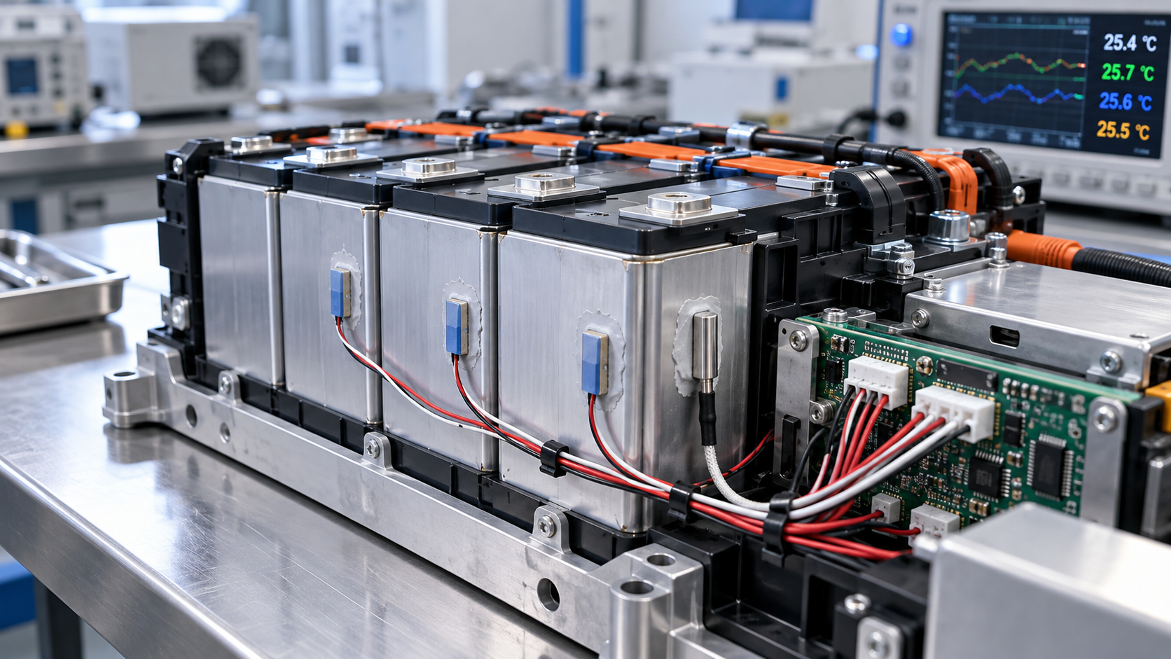
Assembly details deserve equal attention. Adhesive thickness, contact pressure, air gaps, encapsulation, and nearby conductive structures can change both steady-state offset and transient response.
Adding sensors can improve temperature coverage when the extra locations resolve meaningful gradients. Sensor count alone does not establish adequate coverage or dependable fault detection.
How Fast Must the Measurement Respond?
Static accuracy describes agreement after temperatures stabilize. During rapid heating, a sensor can meet its steady-state specification while temporarily under-reporting the temperature relevant to protection.
For an approximate first-order response under a sustained temperature ramp, lag error is roughly the temperature rise rate multiplied by the effective time constant.
If the relevant surface warms at 0.2°C per second and the installed time constant is five seconds, the approximate lag is 1°C under those assumptions.
Real battery behavior is more complex, so use this calculation for screening. Validate the complete sensor assembly under representative mounting, thermal paths, and operating transients.
Supplier response-time data measured in liquid or moving air may not represent a sensor bonded to a cell through adhesive and protective encapsulation layers.
The total delay also includes channel scanning, digital filtering, communications, software decisions, and actuator response. Faster sampling alone cannot remove delays elsewhere in the system.
Temperature sensing should also be assessed within the broader battery safety concept. Sensor accuracy alone cannot establish timely detection of every rapidly developing internal failure.
Where Do Chemistry and Fast Charging Change the Requirement?
Cell chemistry influences permissible operating conditions, but chemistry names alone cannot determine sensor tolerances. Use the cell supplier’s validated limits and the vehicle’s operating strategy.
Cold charging requires particular care because lithium-plating risk depends on temperature, current, state of charge, and cell design. An over-reading sensor may enable charging prematurely.
At elevated temperatures, an under-reading channel can delay charge derating or cooling intervention. Repeated exposure can also affect aging, even below immediate protection thresholds.
Aggressive charging profiles may leave less room for measurement uncertainty and dynamic lag. Better temperature information can support performance only when cell limits remain respected.
Specify accuracy across the relevant operating range, with particular attention near decision thresholds. A strong room-temperature result does not prove adequate cold-charge or hot-charge performance.
What Validation Evidence Should Engineers and Buyers Request?
Request performance data for the supplied assembly and intended circuit configuration. Bare-element specifications leave important questions about harnesses, encapsulation, mounting, and production variation unanswered.
Validation should combine controlled accuracy measurements with installed-pack testing. The first establishes measurement-chain performance; the second reveals gradients, contact effects, and behavior during vehicle operation.
- Accuracy across the specified temperature range, especially near control thresholds.
- Response measurements using representative mounting materials and geometry.
- Performance across supply, electronics, and relevant environmental conditions.
- Drift after thermal cycling, humidity, vibration, and application-specific exposure.
- Open-circuit, short-circuit, intermittent-connection, and plausibility-diagnostic coverage.
- Production test limits, traceability, and controls for material or process changes.
Compare readings against a reference with suitable uncertainty and a documented calibration chain. Account for chamber uniformity and differences between reference and sensor locations.
Laboratory precision can be misleading if the reference and production sensor experience different temperatures. Record stabilization criteria and mounting arrangements so results remain interpretable.
End-of-line testing should verify the characteristics it can actually detect. Electrical resistance checks, for example, do not necessarily demonstrate correct thermal contact after installation.
Automotive qualification supports component reliability assessment, but it does not replace application validation or establish that a particular sensor location protects the complete battery system.
When Is Paying for Tighter Accuracy Worthwhile?
Tighter accuracy creates value when measurement uncertainty is a significant constraint on charging performance, usable operating range, cooling efficiency, or protective margins under validated conditions.
It creates less value when the dominant problem is an unmeasured gradient, unstable mounting contact, excessive filtering, or a model that poorly estimates cell temperature.
Compare alternatives using total implementation cost: sensor price, calibration, assembly controls, electronics, validation, warranty exposure, and the operating performance that each option can support.
For sourcing decisions, require proposed substitutes to meet the same resistance-temperature behavior, installed response, environmental durability, and diagnostic assumptions. Nominal accuracy alone is insufficient.
Specify the Temperature Knowledge Your Battery Needs
The right battery temperature sensor accuracy is the uncertainty your control strategy can tolerate across operating conditions and service life, supported by an explicit error budget.
A defensible specification connects sensor tolerance with electronics, placement, response time, thermal gradients, and validation evidence. That connection determines whether tighter accuracy delivers practical value.
Begin with cell limits and control margins, identify the largest uncertainty sources, and improve those first. This produces a stronger engineering decision than selecting by datasheet tolerance alone.