Displays & Connectivity
Navigation
Send Us A Message
How to evaluate automotive display readability in direct sunlight
Author
Date Published
Reading Time
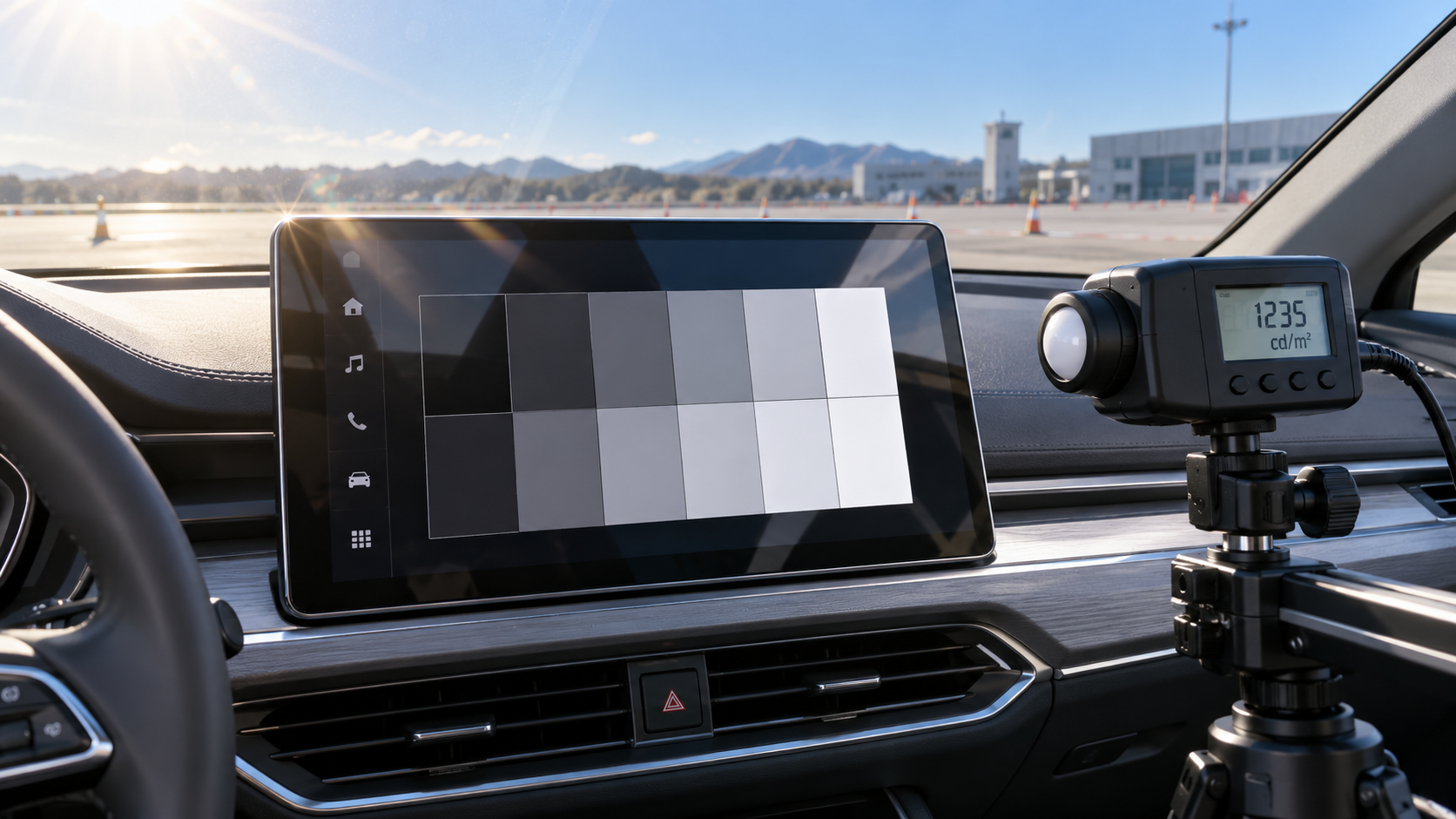
To evaluate automotive displays in direct sunlight, measure how clearly information remains visible with sunlight falling on the installed screen, then repeat the assessment at realistic viewing angles and operating temperatures. Peak brightness alone cannot establish readability. A bright panel can still lose essential detail when reflections raise the apparent black level, polarized sunglasses suppress the image, or thermal controls reduce output.
A useful selection process connects optical measurements to actual driving tasks: reading a warning, identifying the next navigation maneuver, or finding a control during a brief glance. Define those tasks and the vehicle installation before comparing display specifications. This makes the evaluation repeatable and gives suppliers a clear performance target.
Define the sunlight conditions the installation will actually encounter
“Sunlight readable” is incomplete without a test condition. Sunlight reaching a recessed instrument cluster differs from sunlight striking an exposed center display. Screen tilt, windshield geometry, roof shading, and trim reflections can change the result even when both positions use the same panel.
Start with the proposed mounting position and driver eye box: the range of eye positions created by seat adjustment and differences in driver stature. Identify conditions where direct sun reaches the screen, where a bright window is reflected toward the driver, and where illuminated trim appears on the display surface. These conditions can produce different failures and deserve separate checks.
Document the setup sufficiently for another laboratory or supplier to reproduce it:
- Display orientation, mounting angle, and surrounding surfaces.
- Light-source direction, angular spread, spectrum, and illuminance at the display plane.
- Observer or instrument position relative to the screen.
- Cover lens, touch sensor, coatings, bonding, and protective films present during testing.
- Display settings, supply conditions, software version, and temperature state.
Illuminance, measured in lux, describes light arriving at the surface. It does not describe how much reflected light reaches the driver's eyes. Two sources producing the same illuminance can create different glare if their angular distributions differ. Use a controlled source for comparisons, then confirm the selected configuration outdoors and in the vehicle.
Keep direct illumination and reflected glare as distinct test cases. A screen may tolerate broadly distributed daylight yet become difficult to read when the reflected image of the sun or a bright window crosses critical information.
Measure ambient contrast, not just panel brightness
Dark-room contrast describes the difference between a display's bright and dark states without external illumination. Under sunlight, the observer receives emitted display light plus reflected ambient light. That added reflection can make dark regions look gray and reduce the separation between symbols and their backgrounds.
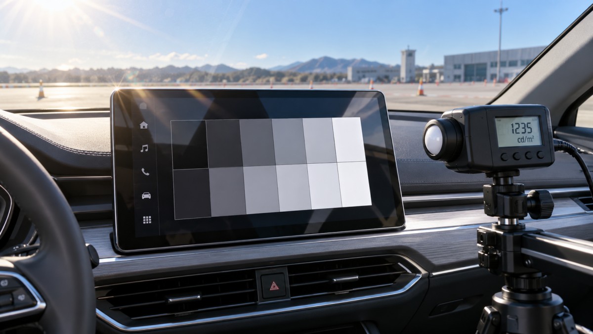
A practical measurement is the ratio between the luminance of a bright feature and its dark background under the same ambient illumination. Luminance, commonly expressed in cd/m² or nits, describes light traveling toward the observer. Measure it from the intended viewing direction, with the sunlight source and screen geometry held constant.
For a simplified case where both regions reflect the same amount of ambient light:
Ambient contrast ratio = (emitted bright-state luminance + reflected luminance) / (emitted dark-state luminance + reflected luminance).
This relationship explains why improving dark-room black level may deliver little benefit when reflection dominates. It also explains why reducing reflected light can be as valuable as increasing backlight output. For actual acceptance testing, measure the illuminated bright and dark regions directly; their reflections may differ, and the simplified assumption may not hold.
Use a calibrated luminance meter or imaging photometer with suitable dynamic range and spatial resolution. A measurement field that includes both a small icon and its background can conceal poor local contrast. Prevent the instrument or fixture from shading the display, and check that stray light entering the instrument does not distort readings.
Measure representative screen locations and content patterns. Full-screen white output can differ from the brightness available during navigation or other mixed content, particularly where power limiting or content-dependent brightness control is active. Record whether automatic brightness, local dimming, and temporary boost modes are enabled.
Evaluate the complete optical stack
Panel specifications do not capture every reflecting surface in the finished assembly. The cover lens, touch sensor, adhesive layers, decorative treatments, and gaps between layers all influence what the driver sees. Compare candidates using assemblies that represent production construction.
Antiglare and antireflective treatments perform different functions. A matte surface can make a sharp reflection less distracting while spreading reflected light over a wider area. That may improve one viewing condition while making another appear washed out. Assess both the reflected image and the readability of fine graphics.
Optical bonding can improve performance by reducing reflection at internal interfaces, but it cannot eliminate reflection from the outer surface. Evaluate the bonded assembly for bubbles, contamination, optical distortion, and changes after environmental exposure. An attractive initial sample does not establish production consistency or long-term optical stability.
Check viewing angles and polarized sunglasses together
Readability measured straight ahead may overstate performance in the vehicle. From another position, luminance can fall, black levels can rise, and colors can shift. These changes matter when a warning relies on both color and shape or when a wide screen places information far from the driver's central viewing direction.
Measure across the defined eye box, including relevant horizontal and vertical angles. Keep the screen's installed tilt in the setup. For each position, assess critical information near the edges as well as at the center. A single center-point luminance measurement cannot show whether the full interface remains usable.
Polarized sunglasses require a separate check. Depending on the display's polarization and optical construction, rotating the glasses or tilting the head can significantly darken the image or introduce color effects. Test representative sunglasses at normal head positions and plausible head tilts, using the final cover assembly.
Do not infer sunglasses compatibility from the panel technology name alone. Polarizers, compensation films, touch layers, and cover materials influence the result. Record any orientation that obscures critical content, and repeat the check with sunlight present rather than relying only on an indoor demonstration.
Determine what brightness survives heat soak
A display may deliver strong brightness when first switched on, then reduce output as its temperature rises. This is especially relevant when direct sunlight heats the cover while the display electronics and backlight generate additional heat.
Evaluate both initial performance and sustained operation after representative thermal conditioning. Log screen luminance, electrical power, relevant temperatures, and brightness-control behavior over time. Record where temperatures are measured: chamber air, cover surface, and internal sensor readings describe different conditions.
Separate a fixed-brightness optical comparison from a system-level test of automatic brightness. The first helps compare assemblies under controlled settings. The second shows whether the vehicle actually commands sufficient brightness when needed. Sensor placement, shading, calibration, and control response can prevent a capable panel from reaching useful output.
Check what happens when the thermal limit is reached. A gradual reduction may make small text unreadable before the whole screen appears noticeably dim. Recovery behavior also matters: after shading or cabin cooling, the system should restore useful output according to the intended control strategy.
Compare electrical demand at the brightness each candidate needs to meet the same readability requirement. Equal brightness settings or equal maximum luminance do not necessarily represent equal performance. A lower-reflection assembly may reach the required visibility with less emitted light, changing its thermal and power requirements.
Use driving tasks to establish pass or fail
Optical measurements identify weaknesses, but they do not fully describe whether a driver can interpret the interface. Readability also depends on text size, stroke width, icon design, background detail, and the time available to understand a message.
Build a compact set of production-representative screens: a navigation maneuver, a warning message, primary vehicle information, and a frequently used touch control. Include the smallest critical text and demanding color combinations. Assess light and dark interface themes where both are intended for use.
Ask whether the intended information can be identified correctly during a controlled brief glance. Use a stationary vehicle or simulator for assessments involving reading tasks and glare. Record errors, hesitation, and missed symbols alongside luminance data. Photographs can document the setup, but automatic exposure and image processing make them unreliable as the sole evidence of readability.
Set acceptance criteria before reviewing supplier results. Specify the content, viewing positions, illumination conditions, thermal state, and measurement method. Apply stricter task requirements to critical warnings than to decorative graphics. A single universal contrast threshold is unlikely to capture every combination of font, symbol, and viewing condition.
If a screen fails, identify the cause before increasing brightness. A reflected window across a warning may call for a change in mounting angle or surface treatment. Fine text may need stronger strokes or a simpler background. These remedies address different mechanisms and carry different cost and packaging consequences.
Make the supplier comparison usable for a sourcing decision
Request results for the complete proposed display assembly, with the test method and operating conditions attached. A peak-luminance figure without temperature, duration, content pattern, and viewing direction leaves too much ambiguity for selection.
Use the same conditions to compare ambient contrast, reflection behavior, viewing-angle performance, sunglasses compatibility, sustained hot-operation luminance, and electrical demand. Review how coatings and optical bonds retain their properties after relevant cleaning, abrasion, and environmental validation. Include production tolerances and more than one sample when establishing confidence in a design.
Keep pass-or-fail requirements separate from preferences such as appearance or purchase price. A weighted score can otherwise allow strong performance in secondary areas to conceal a failure to display essential information. Once candidates meet the required reading tasks, compare the power, thermal, packaging, manufacturing, and sourcing implications.
The next useful step is to give shortlisted suppliers one common test specification tied to the intended vehicle installation. Require evidence that the production-representative assembly remains readable across the eye box, under defined sunlight, and after thermal stabilization. That evidence provides a firmer basis for selection than a favorable brightness specification.
Core Sector // 01
Recommended News
 Displays & ConnectivityHow Can You Confirm Cabin Heat Soak Is Causing Display Blackouts?How can I tell whether display blackouts after cabin heat soak are temperature-related? Discover how temperature logs, hot-versus-cool tests, and power checks help pinpoint the cause.
 Displays & ConnectivityCan you upgrade a car audio system while keeping the factory amp?Upgrade Automotive Audio Systems while keeping your factory amp. Explore speaker compatibility, bass upgrades, and integration tips for clearer sound without costly mistakes.
 Displays & ConnectivityHow to evaluate automotive display readability in direct sunlightEvaluate Automotive Displays in direct sunlight with practical tests for contrast, glare, viewing angles, and heat. Discover how to compare suppliers and select screens drivers can read.